EN
EN

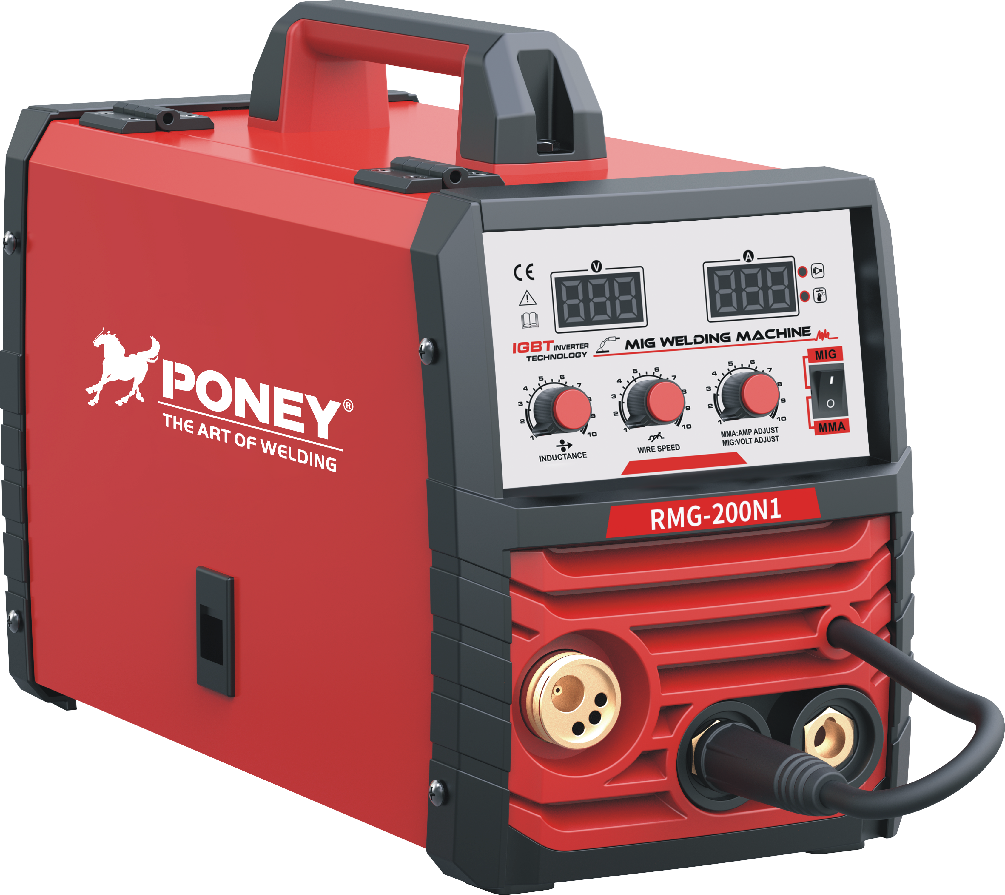
CO2 welding represents one of the most versatile and widely adopted arc welding processes across manufacturing and fabrication industries. When transitioning between thin and thick steel materials, operators must understand how fundamental CO2 welding parameters shift to maintain weld quality, penetration, and structural integrity. The difference between successful welds on thin gauge steel and heavy structural plates lies in precise parameter adjustment, including voltage, wire feed speed, travel speed, and shielding gas flow rates. This article explores the critical adjustments required when moving between these two material thicknesses and explains the engineering principles behind each parameter modification.
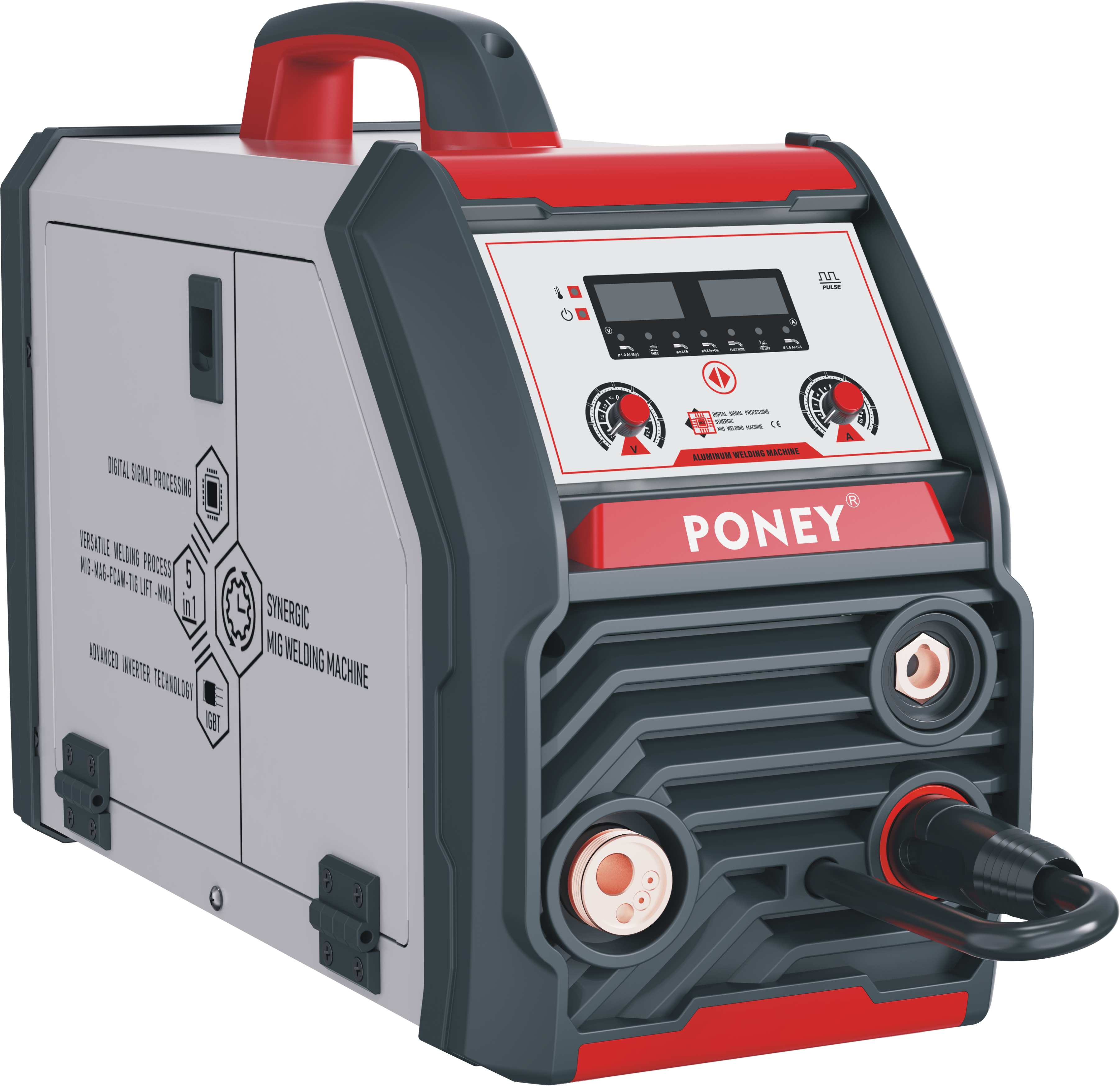
Understanding the relationship between material thickness and CO2 welding setup prevents costly weld defects, reduces rework, and improves production efficiency. Thin steel typically ranges from 0.024 to 0.125 inches, while thick steel begins around 0.25 inches and extends to several inches or more. Each thickness range demands specific CO2 welding configurations to achieve proper heat input, fusion depth, and structural performance. Whether you operate in automotive fabrication, structural steel construction, or precision sheet metal work, mastering these parameter transitions ensures consistent, code-compliant results across your material range.
Voltage and Heat Input Adjustments for CO2 Welding
Voltage Changes Between Material Thicknesses
Voltage is one of the most critical CO2 welding parameters because it directly controls heat input and arc characteristics. When working with thin steel, CO2 welding operators typically use lower voltages, generally ranging from 15 to 18 volts, to prevent burnthrough and excessive spatter. The reduced voltage maintains a cooler arc cone, which allows the welder to deposit material without melting through the thin base metal. Conversely, thick steel requires higher voltages, often between 24 and 32 volts, to generate sufficient heat for deep penetration and complete fusion through substantial material thickness. This voltage increase ensures that CO2 welding heat reaches the root of the joint and creates a strong metallurgical bond across the full cross-section.
Arc Stability and Penetration Control
The arc stability achieved during CO2 welding directly influences weld bead profile and mechanical properties. Higher voltages in thick-material CO2 welding produce a wider arc cone that spreads heat across a larger area, improving heat transfer into dense material. Thin-gauge CO2 welding benefits from lower voltages and narrower arc cones, which concentrate energy into a smaller footprint and minimize distortion. The transition between these voltage settings also affects shielding gas coverage; higher voltages in CO2 welding require slightly increased gas flow to maintain consistent shielding under the broader arc. Many operators implement automated voltage monitoring systems to detect when CO2 welding transitions between material thicknesses and make real-time adjustments that preserve weld quality.
Wire Feed Speed and Deposition Rate Optimization
Feed Speed for Thin Steel Applications
Wire feed speed in CO2 welding governs the amount of filler metal deposited per unit time and directly correlates with travel speed and heat input. For thin steel, CO2 welding typically requires wire feed speeds between 200 and 400 inches per minute to match the lower voltage and heat input parameters. Slower feed rates reduce the total amount of molten metal deposited into the weld pool, preventing puddle overflow and burnthrough on thin gauge materials. The welder maintains better visual control and puddle size management when CO2 welding thin steel with moderate feed speeds. Operators often use pulsed CO2 welding techniques on thin material, where wire feed speed varies cyclically to further reduce average heat input while maintaining adequate fusion.
Feed Speed for Heavy Gauge Steel
Thick steel welding requires substantially higher CO2 welding wire feed speeds, typically ranging from 500 to 800 inches per minute or even higher for rapid production runs. The increased feed rate deposits more filler metal into the joint and generates the higher current necessary for deep penetration through thick sections. CO2 welding on heavy material benefits from continuous, steady wire feed rates because the larger weld pool can tolerate faster deposition without defects like porosity or incomplete fusion. Multi-pass welding on thick steel often employs different CO2 welding feed speeds for different passes; root passes may use moderate speeds for control, while fill and cap passes use higher speeds to improve productivity. The transition from thin to thick material CO2 welding sometimes requires 100 to 200 percent increases in feed speed, representing a substantial parameter shift that operators must plan and validate.
Travel Speed, Joint Geometry, and Technique Modifications
Travel Speed Considerations Across Material Thickness
Travel speed during CO2 welding refers to how quickly the welding gun moves along the joint and profoundly affects weld appearance, penetration, and heat-affected zone characteristics. Thin steel CO2 welding typically uses travel speeds between 8 and 15 inches per minute to maintain adequate arc dwell time and ensure complete fusion without burnthrough. Slower travel speeds on thin material allow the welder to monitor the weld pool visually and make micro-adjustments that prevent defects. Thick steel CO2 welding can support faster travel speeds, often 12 to 25 inches per minute or higher, because the larger thermal mass of the base metal distributes heat without overheating localized areas. The relationship between travel speed and wire feed speed determines the heat input per unit length; maintaining proper ratios ensures consistent CO2 welding bead geometry and mechanical properties across material thicknesses.
Joint Preparation and Pass Strategy
Joint geometry changes significantly between thin and thick steel applications when using CO2 welding techniques. Thin steel typically uses square groove or minimal bevel angles because the entire section can be fused in one or two passes with proper parameters. Thick steel requires V-groove, double-V-groove, or other complex joint designs to provide access for multiple CO2 welding passes and ensure complete root fusion. The transition to thicker material often requires changing from single-pass CO2 welding to multi-pass strategies, which demands adjusting parameters between passes and planning interpass temperature control. Root passes in thick-material CO2 welding use different parameters than fill passes; root passes employ lower currents and travel speeds for control, while subsequent passes use higher parameters for productivity. Understanding how joint geometry drives parameter selection helps welders execute the CO2 welding transition smoothly and produce code-compliant welds.
Shielding Gas Flow Rate and Environmental Factors
Gas Flow Optimization for Different Material Thicknesses
CO2 welding relies on proper shielding gas coverage to prevent atmospheric contamination and ensure sound weld metal. For thin steel, CO2 welding typically requires gas flow rates between 15 and 20 cubic feet per minute to adequately shield the smaller weld pool and shallow fusion zone. The lower flow rate provides sufficient protection without excessive gas turbulence that could disturb the small molten pool on thin gauge material. Thick steel CO2 welding demands higher gas flow rates, usually between 25 and 35 cubic feet per minute, because the larger weld pool and deeper penetration zone require broader shielding coverage. Improper gas flow during CO2 welding transitions creates porosity, oxidation, and mechanical property degradation regardless of voltage and feed speed adjustments. Gas flow must be verified and adjusted whenever transitioning between significantly different material thicknesses to maintain consistent weld quality and eliminate defects.
Environmental Considerations and Process Control
External environmental factors influence how CO2 welding parameters must be adjusted between material thicknesses. Wind and draft conditions affect shielding gas coverage differently on thin versus thick material; thin-material CO2 welding proves more susceptible to wind interference because of the lower gas flow rates and smaller shielded area. Ambient temperature also impacts CO2 welding performance; cold environments may require slightly higher voltage on thick steel to maintain adequate arc energy, while hot conditions on thin material may necessitate lower settings to prevent distortion. Humidity and contamination on the steel surface influence CO2 welding parameter effectiveness; pre-weld cleaning becomes increasingly critical when transitioning from thin to thick material because defects introduced in root passes through thick sections cannot be easily reworked. Professional fabricators establish environmental guidelines and parameter qualification procedures that account for these variables and ensure consistent CO2 welding results across all material thicknesses.
FAQ
What specific voltage range should I use when transitioning from thin steel to thick steel CO2 welding?
When transitioning from thin to thick steel, increase voltage from approximately 15-18 volts for thin material to 24-32 volts for thick material. The exact voltage depends on wire diameter, joint geometry, and desired penetration depth. Always consult equipment specifications and conduct trial welds to verify the optimal voltage for your specific CO2 welding application and material transition.
How much should I increase wire feed speed when moving from thin to thick material in CO2 welding?
Wire feed speed typically increases by 100 to 200 percent when transitioning from thin to thick steel in CO2 welding applications. Thin material generally requires 200-400 inches per minute, while thick material demands 500-800 inches per minute or higher. The exact increase depends on wire size, voltage settings, and production requirements; experimentation within these ranges helps identify optimal parameters for your CO2 welding process.
Does shielding gas flow rate need adjustment when CO2 welding different material thicknesses?
Yes, shielding gas flow must be adjusted during CO2 welding transitions between material thicknesses. Thin steel typically requires 15-20 cubic feet per minute, while thick steel needs 25-35 cubic feet per minute. Proper gas flow prevents porosity and oxidation defects; verify flow rate settings whenever transitioning between significantly different material thicknesses to maintain consistent weld quality throughout your CO2 welding operations.