EN
EN

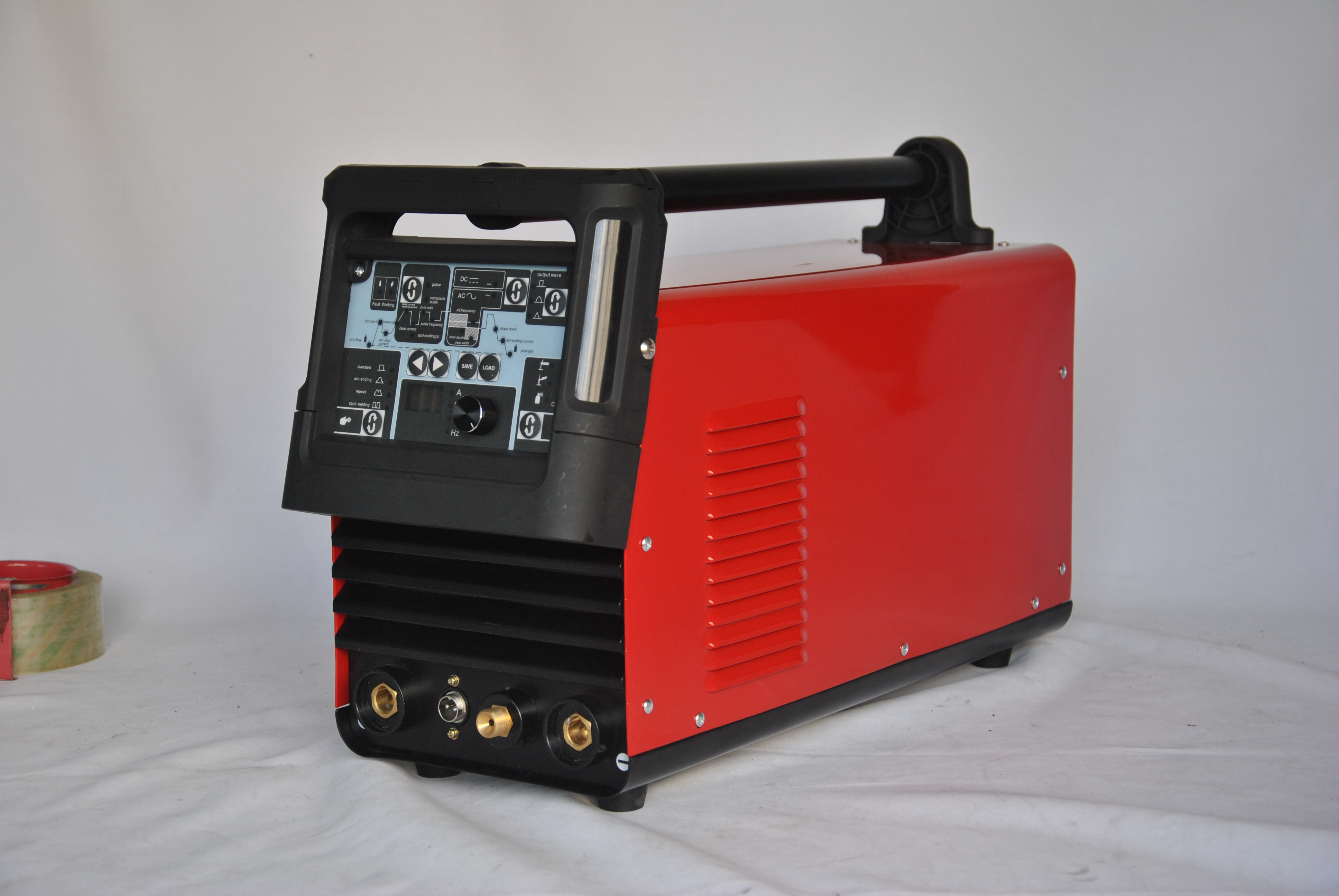
A production-line mig welding machine is far more than a basic welding unit. The mig welding machine built for industrial production environments must integrate robust mechanical systems, precise electronic controls, and operational efficiency that standard workshop equipment simply cannot deliver. Understanding the core design elements that define a mig welding machine for manufacturing ensures you select equipment that will consistently meet high-volume output demands without frequent downtime or quality compromise.
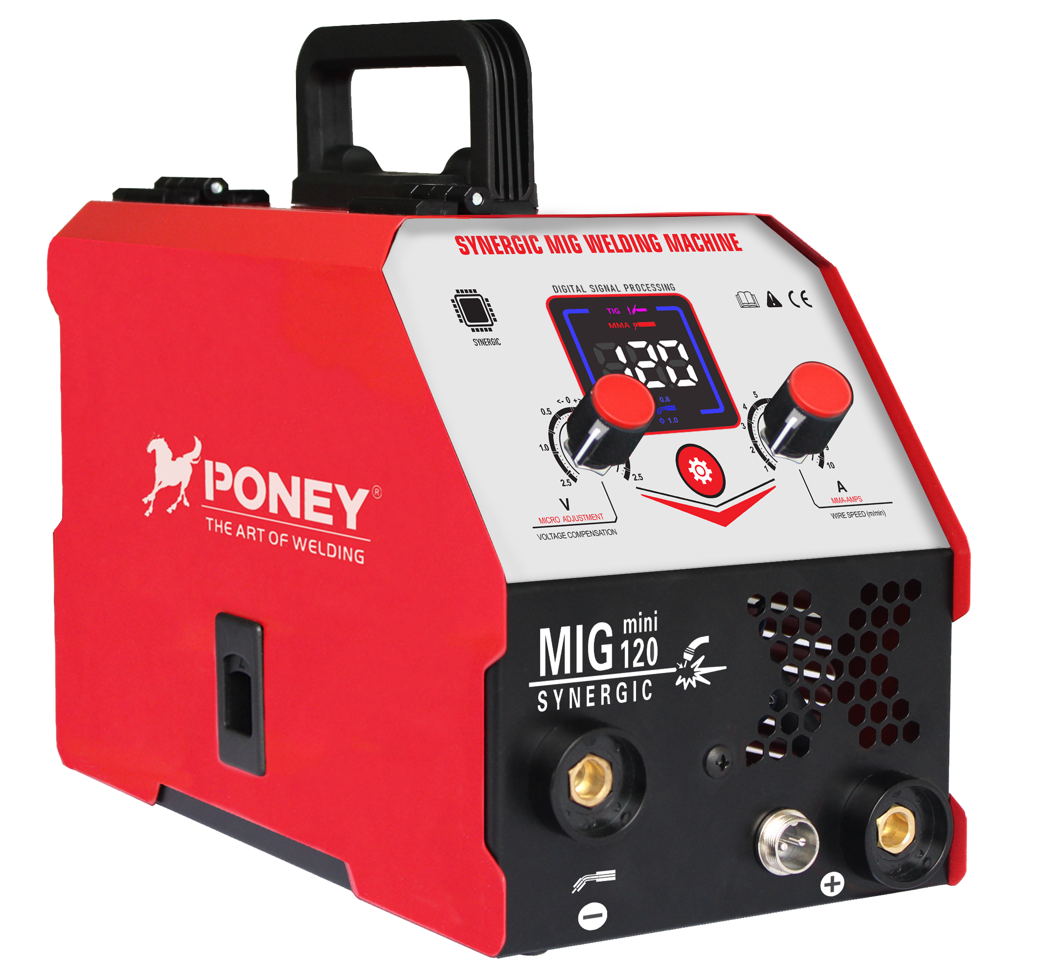
The distinction between a general-purpose mig welding machine and one engineered for production lines lies in five critical design domains: power delivery architecture, thermal management capability, consumable feed precision, duty cycle resilience, and integration flexibility. Each element works together to transform a mig welding machine from occasional-use equipment into a reliable, high-throughput industrial asset that production managers can depend on day after day.
Power Delivery and Electrical Architecture
Industrial-Grade Power Supply Design
A production mig welding machine requires a power supply engineered for sustained current stability across extended operating windows. The mig welding machine transformer and rectifier must deliver consistent amperage output regardless of fluctuating input voltage or continuous load cycling. Industrial mig welding machine power systems typically employ multi-phase power input, advanced SCR (Silicon Controlled Rectifier) conversion, or inverter-based technology to maintain arc stability across varying material thicknesses and welding parameters. This ensures that every mig welding machine weld bead maintains consistent penetration and appearance throughout an entire production shift.
Voltage and Amperage Control Precision
The mig welding machine control circuitry in production environments must enable fine-grain adjustment of both voltage and wire feed speed without manual recalibration between parts. Advanced mig welding machine systems incorporate synergic drive technology, which automatically correlates voltage and wire feed parameters based on a single dial setting. This capability reduces operator error, accelerates setup time between job changes, and ensures that each mig welding machine cycle produces consistent results. For high-speed production lines, this precision becomes essential to maintaining weld quality across thousands of identical welds.
Thermal Management and Duty Cycle Capability
Continuous Cooling System Integration
Production-duty mig welding machine designs must incorporate either air-cooled or liquid-cooled duty cycles that support 100% on-time operation without thermal shutdown. A mig welding machine without adequate cooling will reach critical temperature thresholds and enter automatic shutdown mode, creating costly production gaps. Industrial mig welding machine units often feature robust aluminum heatsinks, active fan cooling systems, or integrated water-cooling jackets around the main transformer and rectifier sections. The mig welding machine cooling architecture directly determines how many hours per shift the equipment can operate at full amperage without thermal derating or emergency shutdowns.
Component Heat Dissipation Strategy
Every mig welding machine sub-assembly generates heat during operation, and production environments demand that this thermal load disperses efficiently. Industrial-grade mig welding machine enclosures employ internal baffles, thermal barriers, and ventilation paths designed to move heat away from sensitive electronics toward external coolers or ambient air. The mig welding machine transformer, inductor coils, and power transistors must all maintain operating temperatures below critical thresholds even during peak summer conditions or when multiple units operate in close proximity. Inadequate thermal design forces a mig welding machine operator to reduce settings during peak hours, directly cutting production capacity.
Wire Feed System and Arc Consistency
Precision Consumable Delivery Mechanism
The mig welding machine wire feeder represents the mechanical heart of weld consistency. Production-line mig welding machine systems require double-drive or quad-drive roller mechanisms that grip the wire with uniform pressure and feed it at exactly the programmed speed without slip or variations. The mig welding machine wire spool and liner configuration must minimize friction and drag, ensuring that shielding gas and filler wire reach the arc nozzle in perfect synchronization. High-performance mig welding machine feeders incorporate electronic feedback sensors that detect wire slippage or tension anomalies in real time and automatically compensate.
Contact Tip and Gas Delivery Alignment
The mig welding machine contact tip, gas nozzle, and wire liner must form a precisely aligned assembly that guarantees consistent arc initiation and gas coverage. Production mig welding machine designs feature quick-change contact tip holders, molded gas cups, and standardized component geometry so that operator changeovers take seconds rather than minutes. The mig welding machine nozzle design must shed spatter efficiently and maintain gas flow density at the arc without turbulence that would degrade shielding. This mechanical precision directly translates into fewer weld defects, reduced rework time, and higher first-pass quality rates on a production line.
Duty Cycle and Industrial Resilience
100% Duty Cycle Architecture
A true production mig welding machine is rated for 100% duty cycle at its specified amperage, meaning it can weld continuously for 60 minutes at full output without thermal shutdown or performance loss. Industrial mig welding machine manufacturers achieve this through oversized transformers, premium cooling systems, and robust component selection. This rating is essential because production schedules assume equipment can run uninterrupted through entire shifts without thermal derating. A mig welding machine with lower duty cycle ratings forces production managers to either limit amperage during peak hours or accept expensive downtime for thermal recovery.
Industrial-Duty Enclosure and Connection Standards
The mig welding machine cabinet design for production environments incorporates reinforced steel construction, sealed electrical connectors, and vibration-dampening mounts that withstand factory floor conditions. Industrial mig welding machine interfaces standardize on heavy-duty 3-phase power inputs, liquid or air cooling connections, gas supply ports, and control signal terminals. The mig welding machine wiring employs professional-grade cable assemblies rated for industrial environments, not consumer-grade connections prone to corrosion or loosening. This rugged engineering ensures that a mig welding machine integrated into a production line remains stable, predictable, and maintenance-efficient across years of intensive operation.
Control Systems and Programmability
Parameter Memory and Job Storage
Production mig welding machine systems must allow operators to store and instantly recall precise parameter sets for each distinct job without manual data entry. Advanced mig welding machine control interfaces feature onboard memory that stores voltage, wire feed speed, gas composition, and other settings indexed by job number. This mig welding machine job recall capability eliminates setup errors, reduces changeover time between production runs, and ensures that operator skill level does not dictate output quality. Some mig welding machine units connect to plant floor networks or USB interfaces to download job parameters directly from centralized production planning systems.
Real-Time Monitoring and Diagnostics
Industrial mig welding machine equipment increasingly incorporates digital display screens showing real-time amperage, voltage, wire feed speed, duty cycle percentage, and fault codes. The mig welding machine diagnostic capability allows maintenance teams to identify worn contact tips, damaged liners, or gas flow issues before they compromise weld quality. Production mig welding machine systems may also track hours of operation, total arc time, and thermal cycling data to schedule preventive maintenance before unexpected failures occur. This transparency transforms a mig welding machine from a black-box tool into a monitored asset that production engineers can optimize and predict.
FAQ
What amperage range should a production mig welding machine support?
A production mig welding machine typically operates between 20 and 500 amperes, with most industrial applications concentrating around 200 to 400 amperes. The mig welding machine amperage range must match the material thickness and joint geometry specifications of your primary product line. A versatile mig welding machine can handle both thin sheet metal and thicker structural sections by adjusting voltage and wire feed parameters within its rated range.
How does a water-cooled mig welding machine differ from air-cooled models?
A water-cooled mig welding machine circulates liquid through the torch cable and main transformer to achieve superior heat dissipation in ultra-high-duty environments. The mig welding machine air-cooled design relies on fans and heatsinks, which is sufficient for most standard production lines. Water-cooled mig welding machine configurations cost more upfront and require cooling unit maintenance, but enable higher amperage output or longer continuous duty cycles when production demands justify the investment.
What consumables define mig welding machine operational cost?
The mig welding machine consumable cost primarily comes from filler wire, contact tips, gas nozzles, and shielding gas. A production mig welding machine operator must regularly replace the mig welding machine contact tip and nozzle as they wear or corrode, typically every 8 to 16 hours of operation. Filler wire and gas expenses scale directly with production volume, so efficiency in mig welding machine design that minimizes spatter and gas turbulence significantly reduces overall operational cost per unit.