EN
EN

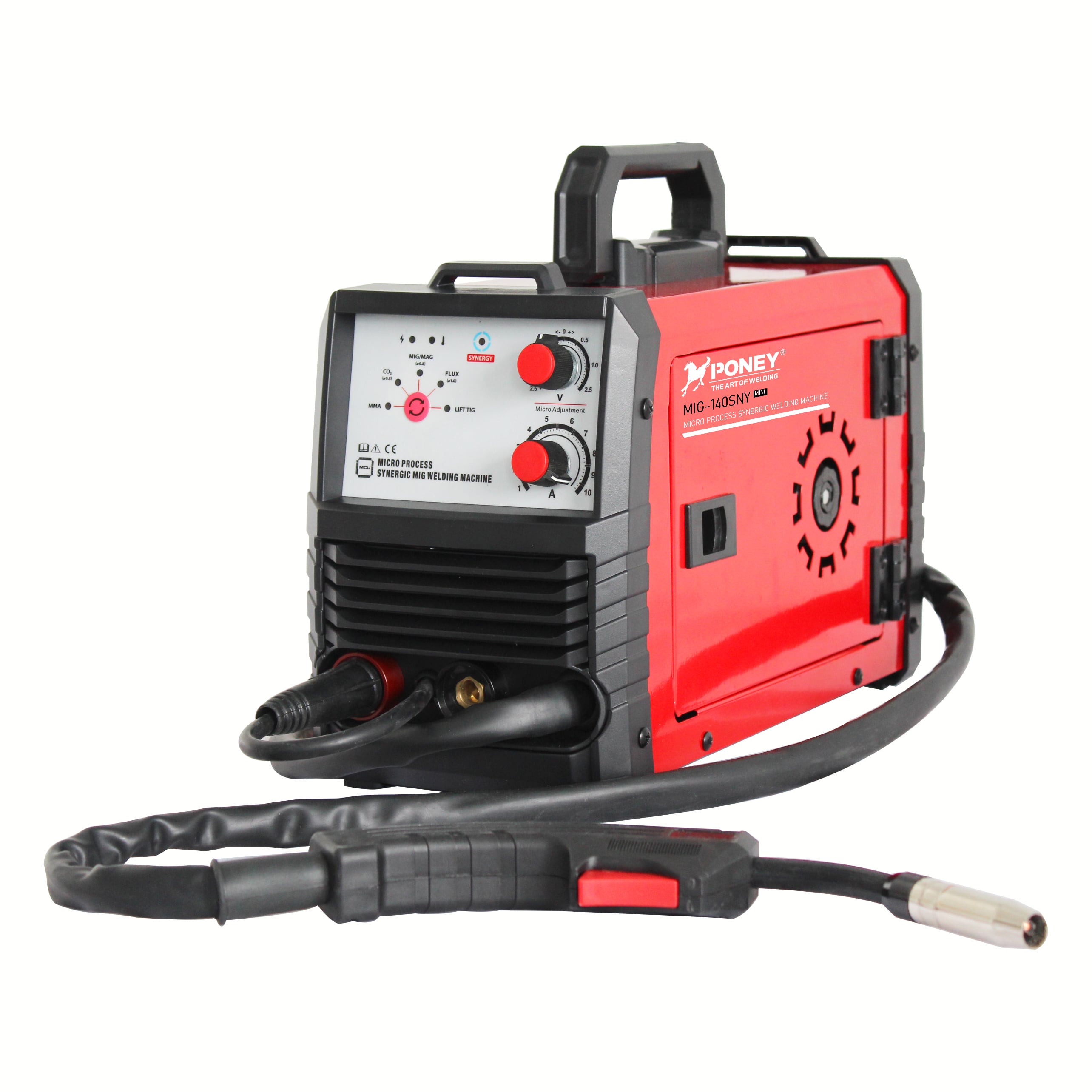
Fabrication productivity hinges on how well a welder is configured for the specific task at hand. A properly configured welder delivers consistent arc stability, optimal penetration, and minimal spatter, all of which directly translate to faster cycle times and reduced rework. Conversely, a poorly configured welder forces operators to compensate with manual adjustments, leading to inconsistent bead quality, increased downtime, and material waste. Understanding how welder configuration affects output across different fabrication tasks enables managers and operators to maximize throughput while maintaining weld integrity.
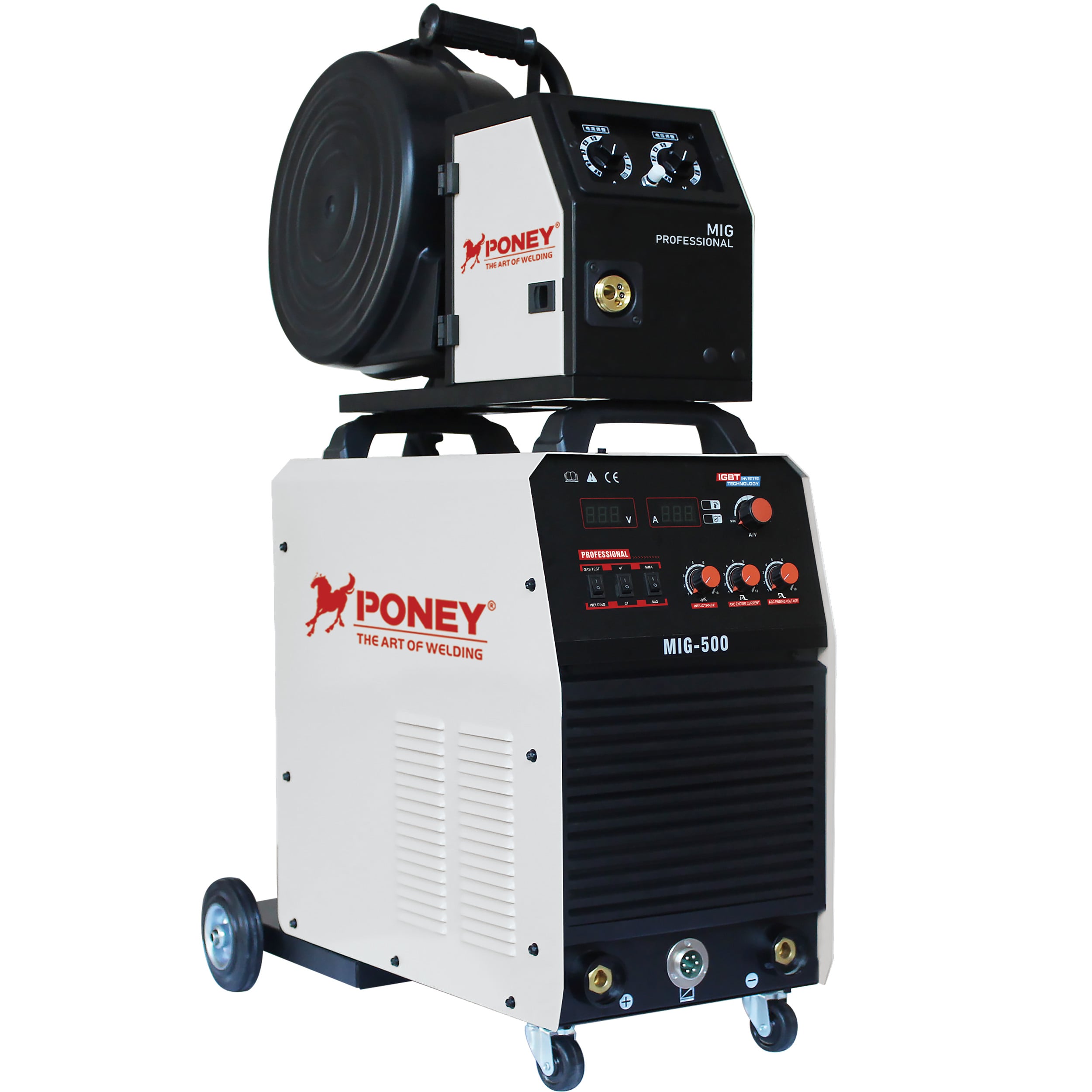
Different fabrication tasks demand distinct welder settings, duty cycle management, and wire feed characteristics. Thin-gauge sheet metal joining requires precise low-amperage control from a welder to prevent burn-through, while heavy structural work demands high-duty-cycle capability and robust wire feed systems. The challenge lies in matching welder configuration parameters to the material thickness, joint design, and production volume requirements of each job. This article examines how strategic welder configuration choices influence productivity metrics across common fabrication scenarios, from high-volume automotive components to low-volume structural assemblies.
Welder Parameter Selection and Task-Specific Throughput
Voltage and Amperage Tuning for Material Thickness
A welder configured with appropriate voltage and amperage settings for the base material thickness delivers immediate productivity gains. When a welder operates within the optimal parameter window for a given material gauge, the operator achieves first-pass weld quality without trial-and-error adjustments. For thin materials under 3mm, a welder set to lower voltage ranges between 16-20V and amperage between 80-120A prevents excessive heat input that causes warping and requires post-weld straightening. This configuration allows a welder to maintain consistent travel speed and reduces the need for grinding or rework, directly improving task completion time.
Thick-section welding above 10mm demands a welder configured for higher heat input to ensure full penetration and fusion. A welder set to 24-28V and 200-300A delivers the energy density required for deep-groove joints without multiple passes. When a welder is properly configured for thick materials, operators complete joints in fewer passes, reducing arc-on time per assembly and increasing the number of completed assemblies per shift. However, if a welder is under-configured for thick sections, incomplete fusion defects require costly repair welding that erases any initial productivity advantage.
Wire Feed Speed Calibration and Deposition Rate
Wire feed speed configuration on a welder directly governs metal deposition rate, which is the primary driver of fabrication productivity in high-volume production. A welder with wire feed calibrated to match the amperage setting maintains stable arc length and consistent bead geometry. For example, a welder running at 250A typically requires wire feed speed between 400-500 inches per minute to sustain optimal arc conditions. When wire feed speed is correctly matched to amperage on a welder, operators achieve higher travel speeds without compromising bead quality, completing linear welds up to 30% faster than with mismatched settings.
In robotic fabrication cells, a welder with precise wire feed control enables higher duty cycles and tighter process windows. A welder configured with closed-loop wire feed monitoring maintains consistent deposition even as contact tip wear progresses, reducing the frequency of parameter adjustments and minimizing downtime. This configuration approach allows a welder to sustain production rates over extended runs, which is critical in automotive and appliance manufacturing where cycle time consistency determines line balance. Conversely, a welder with poorly calibrated wire feed introduces arc instability that forces operators to reduce travel speed, directly cutting throughput.
Duty Cycle Management and Sustained Production Capacity
Thermal Capacity Alignment with Fabrication Demand
A welder rated for appropriate duty cycle relative to the task duration prevents thermal shutdowns that disrupt production flow. Duty cycle represents the percentage of a 10-minute period that a welder can operate at a given amperage without overheating. For continuous production tasks such as tank fabrication or structural beam assembly, a welder configured with 60% duty cycle or higher at the operating amperage ensures uninterrupted arc-on time. When a welder thermal capacity matches or exceeds the task demand, operators maintain steady work rhythm without forced cooling pauses, completing assemblies in predictable time frames.
In contrast, using a welder with insufficient duty cycle for sustained high-amperage work introduces unpredictable downtime. A welder rated for 35% duty cycle at 250A will thermally protect after approximately 3.5 minutes of continuous arc time, forcing a 6.5-minute cooldown before resuming. This configuration mismatch fragments the work cycle and reduces effective operator utilization. For fabrication shops running multi-shift operations, specifying a welder with duty cycle headroom above typical task requirements prevents productivity loss due to thermal limiting, especially during peak ambient temperatures or when ventilation is restricted.
Power Source Configuration and Arc Stability
The power source technology within a welder significantly affects arc stability and spatter generation, both of which influence productivity through rework reduction. An inverter-based welder configured with digital arc control maintains tighter voltage regulation and faster short-circuit response than conventional transformer-based units. This configuration allows a welder to produce smoother metal transfer with less spatter, reducing post-weld cleanup time. In high-mix fabrication environments where a welder must handle frequent material and thickness changes, inverter technology with synergic control programs enables rapid parameter switching without manual calculation, cutting setup time between jobs by 40-60%.
A welder equipped with pulsed MIG capability offers additional productivity advantages in out-of-position and thin-material applications. By configuring a welder to pulse between peak and background current levels, operators gain better control over heat input and puddle fluidity. This configuration allows a welder to be used for vertical-up and overhead welding at higher travel speeds than conventional spray transfer, directly increasing linear inches welded per hour. For fabricators producing complex assemblies with multiple joint orientations, a welder with pulse capability configured to task-specific programs eliminates the need for process changes and electrode swaps, maintaining continuous production flow.
Process-Specific Welder Configuration and Quality-Productivity Balance
Gas Shielding Configuration and Defect Prevention
Proper gas flow configuration on a welder prevents porosity and oxidation defects that require rework and erode productivity gains from other optimizations. A welder configured with gas flow rates between 15-25 cubic feet per hour provides adequate shielding for most MIG applications without excessive turbulence. When a welder delivers consistent gas coverage, operators achieve higher first-pass acceptance rates, eliminating the inspection-reject-repair cycle that consumes productive capacity. For outdoor fabrication or high-travel-speed robotic welding, a welder configured with slightly elevated gas flow compensates for drafts and arc forces, maintaining defect-free production.
Gas mixture selection configured for a welder also impacts productivity through its effect on penetration profile and spatter levels. A welder running on 90/10 argon-CO2 mix produces a more focused arc with deeper penetration than pure CO2, allowing operators to complete single-pass welds where pure CO2 would require multiple passes. This configuration reduces arc-on time per joint by 20-35% in applications involving 6-10mm plate. However, a welder must be reconfigured with adjusted voltage and wire feed when changing gas mixtures to maintain optimal arc characteristics, requiring documented setup procedures to prevent trial-and-error adjustments that waste production time.
Wire Electrode Specification and Welder Compatibility
The wire electrode diameter and composition specified for a welder determine deposition efficiency and influence achievable productivity levels. A welder configured to run 1.2mm wire deposits metal approximately 25% faster than the same welder running 0.9mm wire at equivalent amperage, due to higher current density and improved transfer efficiency. For high-volume production of assemblies with consistent joint configuration, configuring a welder for larger diameter wire maximizes metal deposition rate. However, a welder must have sufficient wire feed system rigidity to prevent bird-nesting and feed interruptions with larger diameter wires, requiring drive roll and liner configuration matched to wire size.
Alloy-specific wire electrodes require welder configuration adjustments to maintain productivity when changing materials. A welder transitioning from carbon steel to stainless steel welding typically requires 10-15% voltage reduction and modified wire feed speed to compensate for different electrical resistivity and arc characteristics. When a welder is reconfigured systematically using documented parameter sets for each material, setup time between production runs drops significantly. Fabrication operations that fail to configure a welder with material-specific programs experience higher scrap rates and slower cycle times as operators iteratively adjust settings, negating the potential productivity of the equipment.
FAQ
What welder configuration changes most impact productivity in thin-gauge fabrication?
Voltage reduction and precise wire feed control on a welder are most critical for thin-gauge productivity. A welder configured with voltage between 16-19V and wire feed speed below 300 inches per minute prevents burn-through and warping that require rework. Additionally, configuring a welder with short-circuit transfer mode rather than spray transfer provides better heat control for materials under 2mm thickness, allowing operators to maintain higher travel speeds without distortion.
How does welder duty cycle configuration affect multi-shift fabrication operations?
A welder with duty cycle rated at least 20% above typical operating amperage prevents thermal shutdowns during sustained production. For fabrication shops running 16-hour or 24-hour operations, configuring a welder with 60% or higher duty cycle at working amperage ensures continuous availability. Insufficient duty cycle on a welder introduces unpredictable downtime that disrupts production scheduling and reduces effective equipment utilization, particularly during summer months or in poorly ventilated facilities.
Can one welder be configured for both thin and thick material fabrication efficiently?
A modern inverter welder with synergic programs can be configured for wide material thickness ranges, but productivity optimization requires documented parameter sets for each application. A welder with digital control and stored programs allows rapid reconfiguration between thin-gauge and heavy-section work, minimizing setup time. However, a welder must have adequate amperage range and duty cycle headroom to handle the upper end of thickness requirements without thermal limiting. For fabricators with distinct thin and thick production volumes, dedicating separate welder units configured and optimized for each range often delivers higher overall productivity than frequent reconfiguration of a single unit.